

ODM Power Transformer Design Essentials for Custom Applications
2026-09-04
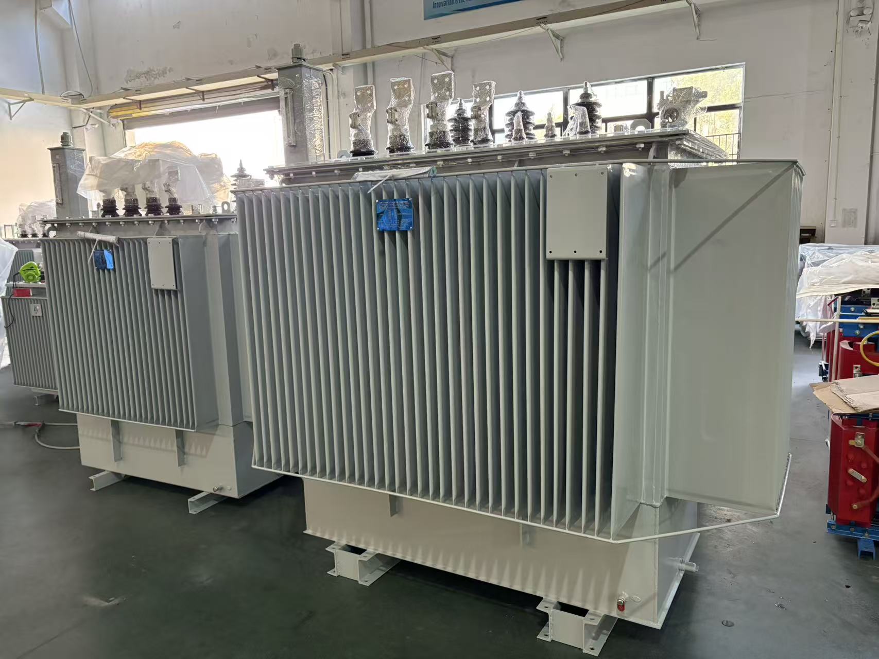
When a standard power transformer can't meet your voltage, size, or thermal requirements, off-the-shelf options quickly become a compromise. Custom ODM power transformer design changes that equation—but only if you get the essentials right. At Lugao, we approach every custom application from the winding structure up, balancing core material, isolation, and load profile to deliver a transformer that fits both your board and your budget. This guide walks through the key design decisions that separate a reliable custom transformer from a costly revision.
What Your Load Profile Says About Core Size Before You Choose a Bobbin
Before you lock in a bobbin, the load profile tells you more about necessary core size than any datasheet headline number. A transformer that runs at a steady 10 W with occasional dips doesn't need the same magnetic cross-section as one that gets slammed with 30 W peaks every few milliseconds. Ignoring this and going straight for a “safe” oversized core usually means a larger winding window than you actually need, extra copper, and a bobbin that physically fights the rest of your layout.
Look at what the load does over time, not just its maximum rating. If the duty cycle is low but the peak current is high, the core may saturate before average power suggests trouble. That's when a slightly larger core with the same bobbin footprint can keep flux density in check, while a continuous low-level load might let you drop a full core size without losing efficiency. The wire gauge and number of turns you can fit on a given bobbin are directly tied to that decision, so a mismatch means either wasted headroom or a hot, cramped winding.
Thermal behavior also shifts the math. A load that cycles hard and then rests allows the core to cool between pulses, so you might tolerate a smaller core than a constant-current application would. But pair that small core with a bobbin that has poor pin spacing for the required wire diameter, and you end up with proximity losses that no amount of core margin can fix. The load profile is the first signal, but core size and bobbin geometry have to be read together if you want a build that doesn't need rework on the bench.
Core Material Selection: Matching Hysteresis Behavior to Switching Frequency
Selecting the right magnetic core material is rarely a simple lookup task—it hinges on how the material's hysteresis loop behaves at the actual operating frequency of the converter. At low switching frequencies, the core is pushed through a wide B-H excursion each cycle, making hysteresis loss (the area inside the loop) a dominant concern. As frequency rises, however, the loop narrows in terms of flux swing but cycles far more often, so even materials with seemingly modest hysteresis loss per cycle can generate unacceptable heat. This is why a ferrite that works beautifully at 500 kHz may be completely unsuitable at 50 kHz, where its saturation flux density limits the usable swing and eddy-current losses in the bulk material start to climb.
Different core families show distinct hysteresis signatures. Manganese-zinc ferrites, for example, exhibit a very square loop at low frequencies but become increasingly lossy above 1 MHz due to residual losses and domain wall resonance. Powdered iron cores, with their distributed air gaps, offer a more gradual saturation curve and lower effective permeability, which helps at medium frequencies (50–300 kHz) where you need higher DC bias capability without the core walking into saturation. Amorphous and nanocrystalline alloys, on the other hand, combine extremely low coercivity with high saturation flux density, but their ribbon construction limits them to lower flux swings unless carefully gapped—making them ideal for high-power, high-frequency applications where hysteresis loss must stay minimal even under large B excursions.
A practical selection process starts with mapping the expected flux density ripple at the target switching frequency, then overlaying that point on the material's published loss density curves (usually given as mW/cm³ versus frequency and peak flux). The tricky part is that the knee of the B-H curve shifts with temperature, and some materials—like certain ferrites—can enter a thermal runaway loop if operated near their Curie point. Engineers often end up choosing a material whose hysteresis loss at the worst-case operating point is low enough to keep core temperature below 100°C without forced cooling, even if that means accepting a slightly larger core than a purely magnetic calculation would suggest. It is this balancing act between loop shape, frequency-dependent loss, and thermal headroom that separates a robust design from one that fails after a few hours of sustained load.
Leakage Inductance Is a Winding Layout Problem, Not a Core Problem
Many designers assume that leakage inductance is tied to the core material or core geometry. In reality, the core plays almost no role. Leakage inductance arises from magnetic flux that fails to link primary and secondary windings. This flux travels through the winding window, insulation layers, and air spaces, not through the core itself. Consequently, even a high-permeability core cannot capture flux that never enters it.
The primary factors controlling leakage inductance are winding arrangement and physical separation. Interleaving primary and secondary layers reduces the effective distance between opposing current paths, forcing more flux to cancel. A split-primary or sandwich winding can cut leakage by half or more compared to a simple side-by-side layout. Reducing insulation thickness or using wider foil conductors also lowers leakage energy storage.
In practice, this means a transformer with a poor winding layout will have high leakage regardless of how good the core material is. Swapping from ferrite to amorphous or nanocrystalline cores changes magnetizing inductance and losses, but barely moves the leakage figure. To fix leakage problems, engineers should first redraw the winding stack-up, not search for a different core.
Potted Transformer Thermals: Why the Datasheet Numbers Rarely Apply
Most transformer datasheets list thermal resistance or temperature rise under free-air convection with a specific mounting orientation—often no potting, no enclosure, and sometimes with a heatsink or copper pour that never appears in your actual design. Once the transformer is potted, the thermal path changes completely. The potting compound replaces the air gaps between windings and core with a material whose thermal conductivity is roughly an order of magnitude better than still air, but that same compound also adds thermal mass and blocks the direct convective cooling of the outer winding surface. The datasheet number was measured before that trade-off existed.
Another mismatch comes from how hotspots move. In an unpotted transformer, the hottest point is usually buried in the center of the winding stack, where heat escapes poorly through layers of insulation and enamel. After potting, the thermal gradient flattens somewhat because the compound conducts heat outward from the winding to the case, but the case itself may now be in contact with surrounding electronics or enclosed inside a sealed housing. A figure derived from an open bench test will understate the rise when the finished potted assembly sits inside a compact power supply with limited airflow. Conversely, a well-designed potted unit with a thermally conductive filler can outperform the bare datasheet value if heat is pulled into a metal chassis or cold plate. Neither scenario is captured by the original number.
The practical takeaway is to treat the datasheet thermal rise as a starting point rather than a guarantee. Measure the actual winding temperature under worst-case load in the final potted enclosure, or at least derate the published figure by a healthy margin until you have that data. Pay attention to the potting compound's filler content—unfilled epoxies and silicones can behave more like insulators, while alumina or boron nitride filled grades can change the outcome by a factor of two or more. If the datasheet does not specify whether the transformer was tested potted or unpotted, assume the more favorable condition and plan accordingly.
Creepage and Clearance: When the Standard's Minimum Becomes the Wrong Target
Designers often treat the tabulated creepage and clearance values in safety standards as a design target. But those numbers are baseline requirements derived under a specific set of assumptions—clean, dry, non-condensing conditions, a defined pollution degree, and a particular overvoltage category. When you design to the exact minimum, you're building a product that passes a bench test, not one that survives the messy reality of field operation. The moment dust settles on a PCB, humidity creeps into a connector, or a transient exceeds the assumed level, that razor-thin margin evaporates.
The real problem is that minimums are static, but operating environments are dynamic. Pollution degree 2 might be fine for a sealed indoor device, but put the same board in an outdoor enclosure with temperature swings and you've effectively shifted to pollution degree 3—where creepage distances need to grow significantly. Similarly, clearance assumes a certain impulse withstand voltage, but if your supply network is prone to higher transients, the standard's numbers no longer protect you. Material choices matter too: some substrates and conformal coatings degrade over time, reducing their comparative tracking index (CTI) and with it the effective creepage capability.
A better approach is to treat the standard's minimum as a starting point for derating, not a finish line. Look at your actual end-use conditions: what's the worst-case humidity, dust accumulation, altitude derating, and switching transient? Then add margin accordingly. Where possible, validate with partial discharge testing or long-term environmental stress tests rather than relying on a one-time hipot check. The goal isn't to barely avoid a flashover on day one; it's to ensure that after years of thermal cycling, contamination, and voltage stress, the isolation barrier still holds. If your design only meets the minimum today, it's already planning to fail tomorrow.
From First Wind to Full Production: The Tests That Expose Hidden Winding Defects
A stator that passes a simple resistance check can still hide turn-to-turn shorts waiting to expand under load. On the first wind, we rely on surge comparison and partial discharge measurements rather than just continuity. These early tests catch insulation nicks and uneven tension before they become warranty returns.
Once the line speeds up, the challenge shifts. In full production, every winding gets a high-potential test and an inductance signature check, but the real value comes from tracking small shifts across hundreds of units. A drift in inductance or a rising corona inception voltage often points to worn tooling or a new spool of wire long before outright failures appear.
The handoff from prototype to volume is where hidden defects usually slip through. By keeping the same pass/fail limits from the first wind through full-rate assembly—and reviewing the borderline units instead of scrapping them silently—we catch the subtle layer shorts and compression damage that only show up after varnish and heat cycling.
FAQ
A catalog unit assumes a mostly steady load, so the core and windings are sized for a narrow operating window. In a custom design, we start with the actual load envelope — including inrush peaks, harmonic content, and the length of overload periods — then adjust conductor cross-sections, core cross-area, and even the magnetic flux density to keep temperature rise within limits across that whole profile. That approach prevents nuisance tripping and premature insulation aging that a standard unit would run into.
Harmonics increase core losses faster than many engineers expect. Standard grain-oriented silicon steel works fine at 50 or 60 Hz with a clean sine wave, but heavy third or fifth harmonic content pushes the flux waveform into regions where hysteresis and eddy current losses climb sharply. For those cases, thinner laminations, domain-refined steel, or even amorphous metal can cut core losses by a noticeable margin. The trade-off is cost and mechanical fragility, so we match the material to the actual harmonic spectrum instead of defaulting to the cheapest option.
Space constraints usually force a move away from simple layer windings toward foil or interleaved configurations that pack more copper into less volume. Split primaries and secondaries also help because they reduce leakage inductance and allow a shorter magnetic path. We often use rectangular or stepped core cross-sections to fill the available footprint more efficiently. The main downside is increased manufacturing time, but for a custom design that is usually acceptable compared to an oversized standard unit.
You cannot rely on a single varnish dip for that kind of environment. A better approach is to use higher thermal class insulation — typically Class H or N — combined with vacuum pressure impregnation to fill all voids in the windings. For exposed terminals, we specify creepage extenders or encapsulated bushings. The goal is to keep moisture and conductive dust from forming a tracking path across surfaces, so we also avoid sharp edges on any metallic parts near the coil.
Sealed enclosures remove convection as a cooling path, so the design has to rely on conduction to the case and radiation from the outer surface. We usually mount the core and coil assembly directly to a heat-spreading plate, use thermally conductive potting or gap filler, and reduce current density in the windings. Sometimes the enclosure itself becomes the heat sink, which means the transformer's hot-spot temperature has to be calculated with the enclosure's external surface area and emissivity, not just the transformer's own surface.
Beyond routine ratio, polarity, and insulation resistance checks, a custom unit needs a temperature rise test under the worst-case load condition, not just nameplate load. We also recommend a partial discharge test for medium-voltage designs and a short-circuit withstand test if the application can see downstream faults. For high-frequency or harmonic-heavy applications, measure losses with the actual waveform rather than a pure sine wave, because the difference can be significant enough to affect thermal margins.
Efficiency and compactness pull in opposite directions because lowering losses generally means more core material and more copper. The practical path is to decide which parameter is truly fixed first. If the footprint is non-negotiable, we explore lower-loss core materials and higher-temperature insulation to push the design harder without sacrificing reliability. If efficiency is the priority, we allow a slightly larger core and optimize flux density rather than running near saturation. Rarely can both be maximized at once, so the conversation has to start with the actual operating cost per watt lost.
Conclusion
When a custom power transformer moves from sketch to bench, the first misstep is often reaching for a bobbin before understanding the actual load profile. Core cross-section should follow from worst-case flux swing, duty cycle, and thermal stress at real operating points—not from a generic power rating. This ties directly to material choice: a ferrite optimized for 100 kHz will behave very differently at 300 kHz once hysteresis losses and remanence enter the picture. And while designers tend to blame the core for leakage spikes, the winding arrangement itself—interleaving, terminations, spacing to the gap—usually dominates that parasitic. Get those three locked before potting is even considered.
Once the transformer is potted, the numbers on a datasheet are close to useless. Thermal impedance changes dramatically with fill material, void placement, and wall thickness; a part that runs cool in open air can cook inside a sealed housing. Creepage and clearance add another layer: meeting the minimum from a safety standard is not a design target when altitude, pollution degree, or field failures are in play. The only way to catch the gaps is through testing every winding from first prototype to production. Impulse, partial discharge, and inductance-at-load checks reveal poor layer insulation, marginal terminations, and unexpected resonances that a simple turns-ratio test misses.
Contact Us
Contact Person: Doreen
Email: [email protected]
Tel/WhatsApp: 8618057712366
Website: https://www.liugaopower.com/