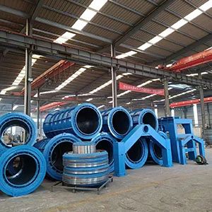

Steel Cage Rolling Welding Machine Manufacturing: Inside a Leading China Company
2026-08-25
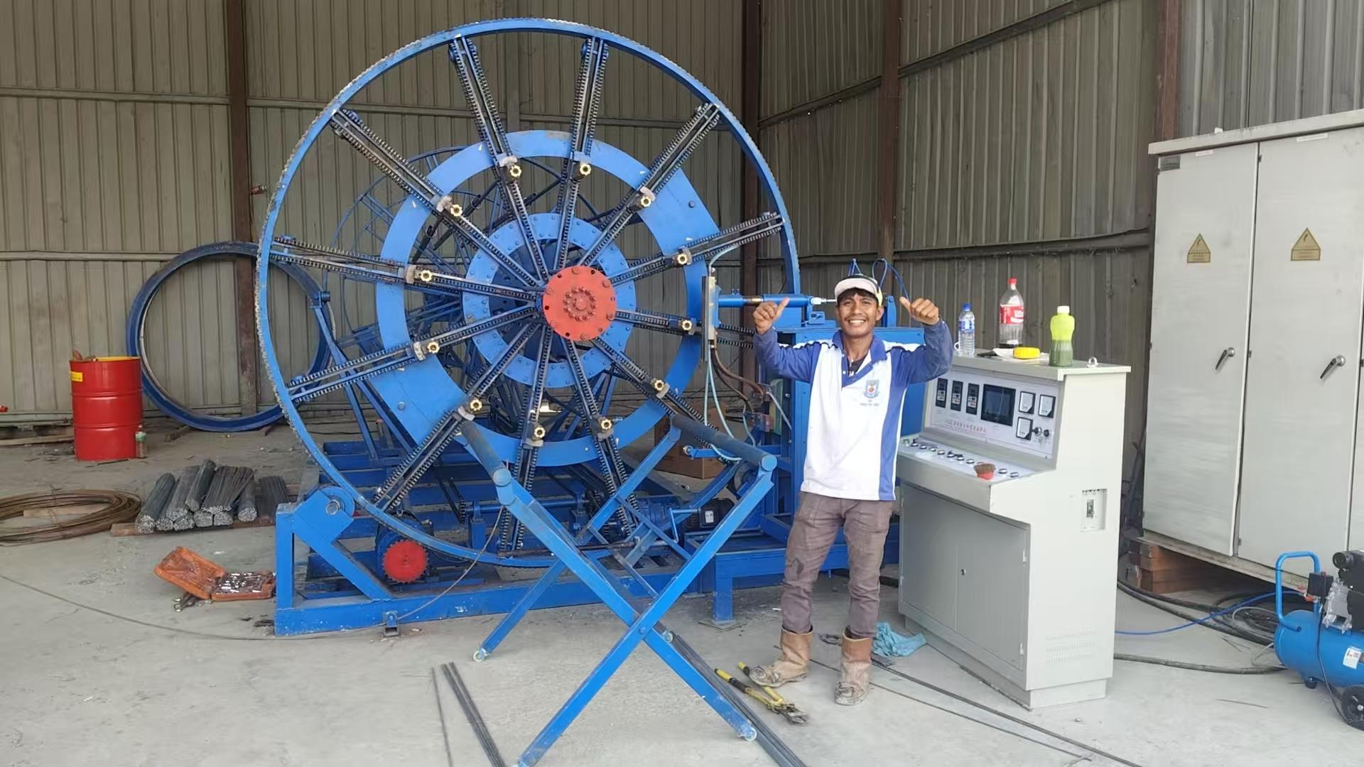
You’ve seen the reinforced concrete cages rising on construction sites, but have you ever wondered who builds the machines that shape them? In China’s competitive equipment landscape, one name keeps surfacing among contractors chasing precision and uptime: Qianfeng Electromechanical Equipment. Instead of another factory tour cliché, this peek inside their operation reveals why their steel cage rolling welding machines aren’t just another line item—they’re a rethink of how rebar cages get made. From jig-free alignment tricks to welding sequences that cut cycle times without sacrificing joint strength, we’ll unpack what actually matters when your next column or pile cage depends on the machine behind it. Ready to see where the real difference hides?
Morning Shift on the Cage Line, a 40-Ton Order in Four Days
At 6:40 the cage line was already awake. Fluorescent tubes buzzed over the roll former, and the first shift crew stood around the whiteboard while Dale ran a thumb down the 40-ton order clipped to the corner. Four days, Friday noon, no overtime approved yet. He circled the two pallets of 6mm wire rod that hadn’t arrived and told the saw operator to start on the 8mm stock already staged by the east bay door. No one said much. The morning air still had that cold-metal smell, and the only real argument was whether to recalibrate the bending jig now or wait until after the first ten cages came off the line.
They broke the work into four-hour blocks. The first block ate through cutting and prepping the bottom mats. A hydraulic shear hesitated on start-up, so Danny shut it down for twelve minutes, adjusted the blade clearance, and ran two test cuts before calling the line back over. By half past nine, eight cages were stacked at the welding station, but the pace wasn’t enough for Wednesday’s target. So Dale shifted two welders off the smaller brackets and put them on the mat frames, leaving the corner braces for the afternoon crew. It wasn’t pretty, but it kept the bottleneck from settling in one place.
By the noon handoff, the board showed 19 cages done and a growing concern about the missing wire rod. The morning shift didn’t solve the whole order, but they left a clean cut list, a marked-up weld sequence, and a note taped to the shear: Do not run the 6mm rod until the new blades go in. A 40-ton order in four days doesn’t leave room for a missed material call or a sloppy setup, and the morning crew made sure neither would start with them.
What Happens When Your Rebar Diameter Changes by 2 mm
A seemingly small 2 mm shift in rebar diameter can ripple through a project in ways that aren't immediately obvious. Most design calculations treat bar size as a fixed input, so when the actual diameter differs from the specified one, the first casualty is usually the effective depth of the concrete section. Losing or gaining a couple of millimeters changes the lever arm between the tension steel and the compression zone, which directly alters the moment capacity. In practice, a slightly thinner bar than specified can push a beam or slab below its intended safety margin, especially near support regions where congestion already compromises concrete placement.
Bond performance also takes a hit. The surface area available for stress transfer between steel and concrete scales with the bar's perimeter, and a 2 mm reduction cuts that perimeter by roughly 6 to 8 percent depending on the original size. This might not sound dramatic, but in lap splices and anchorage zones, even a small loss of bond can lead to premature slip under load. On the flip side, using a larger bar than designed can create its own problems—overcrowding, tighter bend radii than the steel can handle without cracking, and a heavier cage that's harder to position accurately. Field crews often compensate with extra ties or spacers, but those adjustments rarely restore the exact structural behavior assumed in the drawings.
Beyond structural concerns, there's a practical domino effect on cover requirements and crack control. A thicker bar reduces the clear distance to the form face unless the section dimensions are adjusted, which can violate durability requirements for exposure to chlorides or freeze-thaw cycles. Crack width calculations are also sensitive to bar diameter because the bond stress distribution changes; thinner bars tend to produce more numerous but finer cracks, while thicker bars concentrate stress into fewer, wider cracks. Neither outcome matches the original design intent. In short, a 2 mm change isn't just a tolerance issue—it's a chain reaction that touches strength, serviceability, and long-term performance.
Why the Weld Head Gets Rebuilt After Every 500 Cages
Every weld head endures a brutal combination of heat cycling, mechanical impact, and electrical erosion. After roughly 500 cages, the copper alloy tip no longer maintains its original geometry. Small pits and mushrooming from repeated arcing force the operator to compensate with higher current or longer dwell time, which only accelerates the degradation. Rather than chase unpredictable weld quality, the rebuild happens on a fixed interval—it’s cheaper to swap in fresh components than to scrap a run of cages with weak joints.
The contact surface gradually loses its ability to focus pressure on the wire intersection. What starts as a slight rounding of the electrode face becomes a visible crater after a few hundred cycles. That crater scatters the current instead of concentrating it, so the weld nugget forms off-center or not at all. By the 500-cage mark, the failure rate creeps up just enough that a scheduled rebuild avoids the mid-shift surprises that used to happen when pushing electrodes to 800 or 900 cages.
There’s also a thermal factor people rarely mention. The internal water cooling passages in the weld head accumulate scale and lose flow efficiency over time. Even if the tip looks acceptable from the outside, the core temperature runs hotter after hundreds of welds, softening the copper and making it deform faster under load. Rebuilding at 500 cages means replacing not just the tip but also flushing the cooling channels, which restores the head to near-new thermal behavior before it drifts outside the tolerance window.
A Dispatch Bay That Ships to Jakarta, Lagos, and Perth
The dispatch bay hums with a rhythm that doesn't care about time zones. Pallets stacked with mixed freight get tagged, scanned, and routed through a single door that feeds three very different destinations. Jakarta expects the morning rush; Lagos wants consolidated crates that survive humid transit; Perth waits for the weekly refrigerated run. It's not unusual to see a forklift driver juggling labels for all three cities in the same shift.
What makes this bay work is not just logistics software, but a kind of muscle memory. The crew knows which cardboard boxes sweat in the tropics, which shrink-wrap holds through rough seas, and which invoices get delayed at customs. A load for Lagos gets extra bracing on the bottom. A pallet for Jakarta gets lighter strapping so it's easier to break down at a street-side stall. The Perth shipment rides near the dock door on Thursday nights, always last to leave and first to arrive cold.
There's no grand control room, just a whiteboard with three columns and a clock that's always slightly off. One bay, three cities, and a steady stream of decisions made on the floor. It's the kind of place where you learn that shipping to Jakarta is about speed, shipping to Lagos is about durability, and shipping to Perth is about patience.
The Jig Table Trick That Lets One Machine Build Three Cage Sizes
A fixed welding fixture normally locks you into one cage footprint, but here the table’s outer rails stay put while a set of repositionable stop blocks handles the length changes. By moving the stops to pre-drilled index holes, the operator can switch from a 24-inch to a 30-inch or 36-inch panel without unbolting the entire frame.
The trick is in the cross-member locators. Instead of separate tables for each size, the locators slide along a center spine and drop into spring-loaded detents cut for the three common widths. That means the wire grid stays square while the ends are welded, and there’s no need to re-square the assembly after every size change.
What makes it reliable day to day is the paired flip-up side guides. They fold flat for the smallest cage, stand upright for the mid-size, and accept a bolt-in spacer for the largest. Operators can move between sizes in under two minutes, and because the table’s base never moves, the weld gun settings and clamp pressure stay consistent across all three runs.
How a Client’s Sketch Became a Working Prototype in Six Weeks
The napkin drawing had shaky lines and a few question marks scrawled in the margins, but the core idea was unmistakable. Instead of asking for a formal spec, we sat down with the client and walked through each messy annotation, translating their rough vision into a list of tangible functions. That conversation alone uncovered three hidden assumptions that would have derailed the project later.
We broke the next six weeks into two-day build sprints, each ending with a clickable piece of the product rather than a slide deck. The first prototype looked nothing like the final result—it was ugly, slow, and missing half the features—but it gave the client something to react to. By week three, they had stopped referencing the original sketch altogether and started pointing at the screen, saying “that’s not quite it, but this part feels right.”
The real turning point came when we wired the prototype to dummy data that mirrored their daily workflow. Suddenly, the abstract buttons and fields became a tool they could imagine using on a Tuesday morning. We refined the flow twice after that, cut one entire module they realized they didn’t need, and shipped a working prototype on day forty-two. Not a pixel-perfect product, but something they could take to their own stakeholders and say, “This is what we meant.”
FAQ
The floor is organized into dedicated zones for frame fabrication, roller assembly, electrical wiring, and final calibration. Each machine moves through these stations with checkpoints where technicians verify tolerances, weld integrity, and motor performance before it proceeds to the next stage.
They rely on a combination of CNC-guided roller positioning and real-time current monitoring. Operators can save parameter sets for each cage size, and the system automatically adjusts wire feed speed and welding pressure, reducing variation between batches.
The engineering team works from customer drawings to modify roller spacing, add extra welding guns, or change the control interface. Some recent projects included cages with elliptical cross-sections and dual-ring configurations for underground infrastructure.
Most orders come from precast concrete plants, pipe and culvert producers, and foundation engineering firms. A growing share also goes to manufacturers of reinforced concrete poles and tunnel lining segments.
Each unit runs a full production cycle using the customer's specified wire diameter and cage length. The team checks for spatter levels, electrode wear, and dimensional accuracy, then issues a test report with actual measured values rather than nominal specs.
The company uses copper alloy electrodes with chromium-zirconium tips for longer service life. Rollers are machined from hardened steel and coated to resist abrasion, while main drive motors come from established industrial suppliers to reduce downtime.
Beyond remote troubleshooting, they offer on-site commissioning by a technician who trains the operators and maintenance crew. Spare parts for consumables like electrodes and drive belts are kept in regional warehouses for faster dispatch.
Yes, through a modular production approach. Standard subassemblies are pre-built in batches, then configured for each order. This keeps lead times stable—typically 45 to 60 days—even during peak demand periods.
Conclusion
At this leading Chinese manufacturer, the morning shift on the cage line is not just a warm-up; it is where a 40-ton order gets broken into daily targets and welded in four days. Operators watch rebar diameter closely because a shift of just 2 mm is enough to throw off guide rollers, upset spacing, and leave cage joints that look fine but fail under load. The shop has learned to recalibrate on the fly rather than wait for a formal changeover. After every 500 cages, the weld head is pulled and rebuilt—not because it has failed, but because the copper jaws and pressure springs wear in ways that slowly reduce nugget size. Rebuilding on a fixed count keeps every weld consistent instead of waiting for defects to appear.
The same practical thinking shows up in the jig table trick: one machine builds three cage sizes by moving hardened stops and swapping a set of mandrel inserts, so a single line can handle different column and pile specs without buying extra equipment. When a client sent a rough sketch, the engineering team turned it into a working prototype in six weeks by building a short sample cage first and then refining the roll formers and weld timing from measured results. The dispatch bay is equally deliberate. Crates for Jakarta, Lagos, and Perth are packed with different bracing and moisture barriers because each destination has its own handling and climate risks. Load lists, torque marks, and spare consumable kits ride with every machine, which is why repeat buyers rarely ask for remote setup help.
Contact Us
Contact Person: Bill
Email: [email protected]
Tel/WhatsApp: 8615063653526
Website: https://www.qianfengjd.com