

Withdrawable Switchgear Cabinet Manufacturer Reveals Key Design Considerations
2026-10-27
Choosing a withdrawable switchgear cabinet isn't just a box-ticking exercise—it's a decision that shapes uptime, safety, and maintenance for years. MOLDVOLT has spent years engineering around the real-world failures most specs miss. In this post, we highlight the design considerations that separate a dependable cabinet from a liability.
Why Drawout Mechanisms Demand More Than Just Smooth Rails
Smooth rails might make a drawout mechanism feel effortless on the showroom floor, but that first satisfying glide tells you almost nothing about what happens after ten thousand operations. The real test is in the alignment tolerances between the moving carriage and the fixed stabs. A few microns of drift, and you start seeing hot spots at the connection interface. Those heat cycles accelerate oxidation, and before long the breaker that once slid in like silk needs a hard shove and a prayer to make contact at all.
Then there is the locking story. A rail can guide the unit into place, but it cannot tell the operator whether the breaker is actually in the connected, test, or isolated position. That requires a mechanical interlock that is both positive and forgiving. If the interlock relies on a tiny stamped tab that bends after the first misaligned attempt, the entire safety logic falls apart. Designers who obsess over rail surface finish often overlook how the interlock pawl and the position indicator flag interact under vibration or during a rushed racking sequence.
Finally, consider the electrical side. Smooth travel means little if the primary and secondary contacts don't wipe against each other with consistent force. The spring-loaded fingers need to maintain pressure across varying temperatures and minor mechanical wear. When you combine a high-friction rail with poor contact wipe, operators compensate by slamming the carriage, which sends shock loads through the insulating supports. That's how hairline cracks start. So next time someone brags about how smooth their drawout feels, ask to see the contact wear pattern after five years of service, not just the fresh grease.
Interlock Logic That Prevents Costly Operator Errors
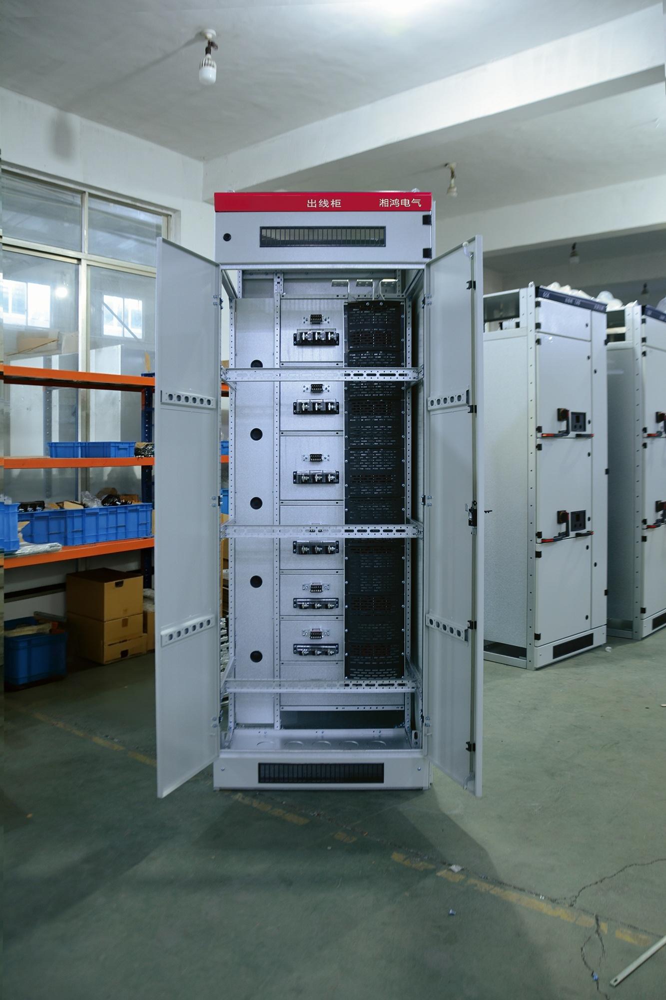
A veteran operator once reached for the vent valve on a pressurized separator without waiting for the upstream isolation to finish. The interlock didn't care about his twenty years of experience. It checked three pressure transmitters, two valve limit switches, and a hardwired safety relay before allowing the vent to crack open. That sequence, simple as it sounds, has stopped more than a few near misses from turning into equipment write-offs.
The logic works in layers, not as a single software flag. A key exchange box forces physical access in a specific order, while the safety PLC runs a permissive string that includes pump running status, line pressure, and door position. On top of that, an independent relay drops out the solenoid power if any input disagrees. When a maintenance bypass is needed, the technician has to plug in a jumper, enter a reason code, and the bypass expires after thirty minutes unless renewed. Forgetting to remove it isn't really possible.
The trick is designing interlocks that don't get bypassed out of frustration. If every minor step requires a supervisor login and a three-minute wait, operators will find a way around it. Instead, the best systems use a quiet, predictable logic: the machine refuses an unsafe action, shows exactly which condition is missing, and resets with a single push after the condition clears. That balance keeps costly mistakes rare without making normal operation feel like a hostage negotiation.
Busbar Layouts That Lower Heat and Simplify Future Expansion
In densely loaded distribution equipment, busbar heat rarely comes from total current alone—it often builds up where current crowds near conductor edges or where adjacent phases interact through proximity effects. A flat, closely spaced parallel layout can create uneven current density and force derating even when the cross-sectional area looks adequate. Splitting each phase into two or more thinner bars and interleaving them as A-B-C-A-B-C, rather than grouping all A bars together, balances the magnetic fields between conductors, lowers effective AC resistance, and reduces operating temperature for the same amount of copper.
Future expansion benefits from treating the busbar system as a set of removable modules instead of one continuous welded or hard-bolted run. Short, bolted flange joints at standard intervals allow a new branch or tap to be added without dismantling the existing bars. Leaving a few unused support brackets or busway tap-off points, and keeping bend radii clear, means a later extension can be completed with prefabricated elbows or T-off units rather than a full redesign.
Physical orientation also matters for heat. Mounting bars with their wide faces vertical instead of horizontal improves natural convection, reduces dust accumulation, and helps hot air leave the top of an enclosed busway. Small ventilation gaps at section joints—sized to maintain the required ingress protection—can lower steady-state temperature rise under continuous load. Together these layout choices reduce thermal stress while keeping the system easy to adapt as load grows.
Arc Containment Without Sacrificing Cable Access or Ventilation
Traditional arc containment often forces a trade-off: seal everything tight to stop the blast, or leave openings for cables and airflow and accept the risk. This design breaks that pattern. The enclosure uses a labyrinthine vent path that lets heat and gases escape at a controlled rate while still blocking direct line-of-sight to energized parts. Cables enter through staggered, rubber-lined ports that maintain their seal under pressure but can be reconfigured in minutes without special tools.
What makes it practical is the way the internal baffles are angled. They don't just absorb arc energy; they redirect it away from the cable entry zone. So you can run multiple large-gauge conductors through the bottom or side without adding bulky external junction boxes. Maintenance crews can swap out damaged sections or add new circuits without breaking the containment rating, because the ports are individually rated and tested, not just the enclosure as a whole.
Ventilation gets the same careful treatment. Instead of a few large vents that compromise the arc rating, there are dozens of small, offset openings that create a natural chimney effect. Hot air rises and escapes through the top while cooler air is drawn in from below. Under normal operation, internal temperatures stay low enough to protect sensitive electronics. During an arc event, the same vents channel the pressure wave upward and away from personnel, reducing the chance of a secondary explosion or flashover.
What Field Data Reveals About Contact Wear and Teardown Intervals
Real-world operational records tell a very different story from accelerated lab tests when it comes to contact wear. In the field, load currents fluctuate unpredictably, switching frequencies vary with production demands, and environmental factors like dust, humidity, or vibration introduce wear patterns that simply don't show up under controlled conditions. By analyzing years of maintenance logs and failure reports from actual installations, engineers have found that contact erosion is rarely linear — instead, it progresses in fits and starts, often accelerating only after a certain number of operations or after exposure to specific overload events.
One consistent finding from field data is that nominal teardown intervals, often based on manufacturer estimates or standard industry practice, rarely match the true wear rate of contacts in a given application. For instance, contacts in high-cycle but low-current circuits may show minimal erosion even after tens of thousands of operations, while those in high-inrush or inductive load circuits degrade far sooner than expected. By correlating actual contact resistance measurements, visual wear inspections, and operational history, maintenance teams can identify the real threshold at which contact replacement becomes necessary — often extending intervals significantly without increasing failure risk.
Perhaps most importantly, field data highlights the value of condition-based maintenance over rigid schedules. Instead of tearing down contacts on a fixed calendar basis, organizations that track individual contact wear trends can schedule interventions only when measurements indicate approaching limits. This approach not only reduces unnecessary downtime and parts consumption but also catches abnormal wear early, before it leads to contact welding or catastrophic failure. The key is to collect and review the data consistently — those who do often discover that their previous teardown intervals were either far too conservative or dangerously optimistic.
Grounding Paths That Stay Reliable After Decades of Switching Cycles
Long-term reliability in grounding paths comes down to more than initial contact resistance. Each switching cycle nudges contact surfaces, scuffs oxide layers, and redistributes the microscopic debris that builds up over time. A path that measures fine on day one can slowly lose its grip if the contact geometry allows fretting or if the materials selected cannot handle repeated micro-arcing. The real question is whether the conductive interface can settle into a stable low-resistance state, not just pass a single continuity test.
Decades of operation expose weaknesses that short-term tests miss. Mechanical wear on pivot points, loosening of bolted joints from thermal expansion, and gradual creep in spring tension all contribute to rising resistance. In some designs, a grounding strap becomes the silent failure point because it carries no current under normal conditions, only during faults. That means the path must remain clean and mechanically sound without the benefit of regular arcing to burn through corrosion. Choosing materials with matched hardness, using sealed or gas-tight joints where possible, and designing for a slight wipe during each operation can keep those paths stable long after the switch has passed its millionth cycle.
FAQ
Many people focus on the breaker itself and forget the door interlocks, racking position switches, and grounding switch coordination. A well-designed cabinet won't let you rack the truck in or out unless the breaker is open, and it should prevent closing the breaker unless the truck is fully in service or test position. Field retrofits often break these sequences if the logic isn't clearly mapped early.
Keeping the main busbars in a separate metal-enclosed compartment reduces the chance of a single fault taking down the whole lineup. It also makes inspection and maintenance less intrusive because you can access one section without exposing adjacent live parts. Some designs skimp on partitioning to save cost, but that directly increases arc flash exposure and outage time later.
Cable compartments are often squeezed because the truck mechanism and current transformers take priority. If you don't lay out the cable entry and bending radius for the largest expected conductor size, installation becomes slow and the terminations run hot. The better designs leave enough height and side clearance for stress cones and lugs without forcing sharp bends.
It keeps the temperature rise within limits under continuous load, especially around the main contacts and bus joints. Passive venting through top and bottom louvers works up to a point, but if the room ambient is high or harmonics are present, you may need forced airflow or de-rating. Dust filters add maintenance burden, so the layout should balance airflow path with easy filter replacement.
It's one of those details that causes nuisance trips if ignored. The sliding contacts or multi-pin plug must engage consistently every time the truck is racked, with enough wipe and contact pressure. If the alignment has too much play, you get intermittent CT or control circuit connections that are hard to diagnose because they only fail in certain positions.
Service means the primary contacts are fully engaged and the breaker can be closed. Test position disconnects the main circuit but keeps the auxiliary circuits connected, so you can exercise the breaker and check logic without energizing the load. Isolated position breaks both primary and secondary connections, so the truck can be safely withdrawn for maintenance. Good mechanical stops and clear position indicators prevent operating mistakes.
It's the difference between safe maintenance and a serious incident. The earthing switch should be interlocked with the truck position so you can only close it when the truck is withdrawn or isolated. Some designs also require the earthing switch to be open before the truck can be racked back in. If the interlock is mechanical rather than just key-based, it's much harder to defeat accidentally.
The cabinet structure is designed to withstand internal arc pressure and vent hot gases through a designated relief duct rather than blowing the doors open. Hinges, latches, and panel thickness are tested under fault conditions. Door seals and internal barriers direct the pressure safely. It's not just about thickness; the weak points have to be controlled so the failure occurs in a predictable direction.
Conclusion
Drawout switchgear may look like a simple rack-and-roller arrangement, but any manufacturer with real field experience knows the mechanism has to survive far more than smooth rails. Repeated insertion and withdrawal under load, misalignment from uneven floors, and worn guide blocks all contribute to premature contact degradation if the carriage isn't engineered with positive locking at both service and test positions. The interlock chain matters just as much: a well-designed unit won't let you rack in a closed breaker, won't let you open the door while the breaker is in the connected position, and won't let you bypass the shutter system with a screwdriver. These are the details that prevent serious arc-flash injuries, not just nuisance trips.
Thermal performance and arc containment often fight each other unless the busbar layout is planned as a system. Vertical risers with generous phase spacing and short horizontal runs reduce hot spots, while dedicated arc plenums and pressure-relief flaps keep an internal fault from turning into a room-wide event — without choking off the cable compartment or blocking ventilation. Field data from decades of service shows contact wear is rarely linear; most erosion happens in the first and last ten percent of a racking stroke, which means teardown intervals should be based on operation count, not calendar years. Finally, the grounding path deserves more than a braided strap: busbar-to-frame bonds with Belleville washers and silver-plated contact surfaces hold their impedance stable through thousands of switching cycles, ensuring a reliable fault path long after the paint has worn off the guide rails.
Contact Us
Contact Person: Hellen
Email: [email protected]
Tel/WhatsApp: 86-13634205622
Website: https://www.voltcabinet.com